Horizontal-Flow
Reasons for Horizontal Flow versus ALL other flow patterns.
Again, this is covered in greater detail on the main website but hopefully, these animated graphics should emphasise the importance of what is probably the real basis as to why ERIC Endless River Systems have been produced in both ready-made and DIY units.
I will cover the mechanical stage of the ERIC units in more detail later but this page covers only the biological stages of all popular pond filter flow patterns as well as ERIC designs.
Perhaps it is first best to detail what the ultimate requirements would be in order to provide perfect biological filtration to our pond systems.
To explain it in mere words is simplicity itself and can be further explained by the following sentence.
(NB. ANY inert and thus non-toxic material will allow bacteria to form on its surfaces when submerged in a constant flow of water within a filter box.)
However, to achieve this perfectly in practice is almost impossible! Many have tried and all have failed over many years in both aquarium applications and pond applications. We have had ancient downward-flow; upward-flow; circular upward-flow; shower applications; pressurised applications and. of late, I am suggesting horizontal flow applications.
In view of this then the best principle to adopt is the one that produces the best results from the available options.
One thing is certain and that is a river situation is the most ‘natural’ flow pattern of all these applications. However, it is best that we briefly consider all these flow patterns yet again in order to find out why there has to be ‘a best of the bunch’ and, if so, just how much ‘better’ it is than the others. Once again, if we must admit that we will never have true perfection here then it is very wise to consider using the very best alternative available to us. I feel that covering all these methods in fine detail is of GREAT importance despite the fact that many consider them to be ‘long-winded’.
I must point out that I am not carrying out any form of ‘witch hunt’ here, instead I am merely trying to get across some information that may stimulate thoughts amongst some readers. Of course, these texts can be taken to others in this world who are officially qualified to be able to comment on my findings below and I do not consider anything in the texts to be anything other than basic common sense.
INDEX
- Downward Flow
This very early DOWNWARD-FLOW design is hardly worth a mention and was first employed…
- Upward Flow
This next example shows the UPWARD-FLOW design first employed in the early 1980’s…
- SHOWER FILTER SYSTEMS
Shower filter systems are, thankfully, much safer and more effective biologically than the previous applications…
- PRESSURISED POND FILTRATION UNITS.
I think I have made my views extremely clear regarding these disasters on my main website….
- HORIZONTAL FLOW PATTERNS
Horizontal Flow patterns are also only mildly useful biologically if used in standard-sized boxes as follows…
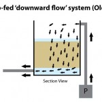
Downward Flow
This very early DOWNWARD-FLOW design is hardly worth a mention and was first employed when most of us had never even heard the words ‘biological filtration’ used before. Reasoning behind it was that the falling water would pass through a strainer-type media and any debris would be trapped inside the media itself.
Upward Flow
This next example shows the UPWARD-FLOW design first employed in the early 1980’s and still the most used system today around the world in all its various manners and guises.
Some of these guises are pump-fed with gravity return; gravity-fed with pump return; surface side exit; surface central exit; surface trough exit; circular upward-flow patterns; multiple chamber units; aerated fluidised media systems and many other variations. Again, these relate to a body of water moving upwards in any given container/box.
The next illustration below shows a side off-take box with heavily aerated semi-buoyant plastic media media as opposed to fixed-position block media, this method is more commonly used in intensive fish farming applications.
The intention is that ALL upward flow incoming water will touch ALL parts of the rapidly-moving media surfaces as it rises. Visually this looks very convincing as a result of it appearing to be ‘busy’ but, as in the example given above, the incoming water, with impetus, merely continues to track directly to the side exit where it is continually pulled towards by the pump.
The majority of heavily-aerated media particles still remain in the surrounding water completely untouched by the constant incoming supply that passes through the ‘invisible tube’ directly to the exit.
This leads to another very true fact, which is, as water rises uniformly through a suspended captive bed of inert surfaces (a filter media barrier), then this will supply ALL media surfaces with a constant flow rate of water – and it does just that, perfectly!
The very moment that water is allowed to overflow the top of the box by exit pipe or be sucked off the top of the box by pump then disaster results. This ‘disaster’ comes by the name of ‘tracking’ as displayed with the above animations. This is simply explained by the fact that incoming water to the box, either by gravity or by pump has impetus, motion, movement, force or current behind it – call it what you will.
This incoming, moving water has one idea in mind and that is to get to the point of exit at the top of the box, which also has equal movement – either by gravity or by suction.
As can be seen, this reduces the constant coverage of the media surfaces to a pitiful usage of only 15% of the surfaces contained within the box. In truth, the box may well be 85% smaller in dimensions for all the actual use it is.
The only way this problem can be resolved is to empty the entire box in order to find the stagnant water, and then throw it away – and as regularly as is possible. This however does not have any effect on the coverage of the biological surfaces within the box when re-started. Furthermore, by linking additional identical boxes together as ‘multi-chamber’ applications, this merely complicates the matter further and only increases the amount of stagnant water within the overall system accordingly.
The first of these systems were employed outside of Japan around the early 1980’s – almost 30 years ago, needless to say, thirty years of experience has resulted in being able to address these significant shortfalls today. As we all know, better designs will usually replace older less efficient ones in just about everything we use.
The trouble is that some other people listening or reading, actually believe them – some have even been seen to congratulate them! Let’s take a real example here of a system containing 20,000 gallons for ease of calculation purposes. By foolishly taking the 10% recommended by the guru, this requires a filter box or boxes that retain 2,000 gallons of the system’s water.
To give one idea of the box dimensions required to hold this volume it would be a perfect single cubic box with dimensions of just a touch over seven feet or, to give another example, a series of five, four feet cube boxes, linked together in order to hold the same amount of water. The task now is to get ALL the incoming water, at whatever flow rate is applied, to pass through AND OUT of these boxes constantly. From the illustrations already given, this is a pure impossibility and simply produces huge amounts of still, unmoving and stagnating areas of toxic water within the boxes that have no possible chance of passing on their contaminants to the bacteria waiting on the media surfaces.
Percentage figures such as these are spouted by those who have not one single idea as to how an efficient filter box needs to perform to the best capabilities of its maximum dimensions. One thing is certain, and that is we need to pass ALL incoming water over ALL biological surfaces as quickly as is reasonably possible and then get ALL of that same processed water the hell OUT of the box and AS RAPIDLY AS IS POSSIBLE because we need to make ALL available space for ALL the new incoming water!)
To summarise on the subject of ALL upward-flow boxes in ALL their guises and ALL of their multi-chambers, the truthful answer is the same for ALL.
SHOWER FILTER SYSTEMS
Shower filter systems are, thankfully, much safer and more effective biologically than the previous applications and it is painfully obvious that NO possible stagnation of water can occur at all.
It goes without saying that open falling water will stimulate substantial beneficial dissolved oxygen content just in its action. Some of these units are used as ‘add-on’ items whilst others, like the Bakki Shower, designed, used and promoted by Mr. Micheo Maeda of the Momotaro Koi farm, are stand-alone biological stage filter systems. From reports given by several users, there is a very real need for a mechanical stage prior to these Bakki Shower units.
As to best media choice for use in these troughs there is no doubt at all that the porous and naturally costly ‘Bacteria House’ fired clay section is the only real serious media choice available for this method. However, like all other things in life, there are those around who wish to capitalise on the idea by using cheaper (and MUCH less effective) media beds.
In truth, the containers, like all other containers, are merely boxes and the real secret of the Bakki Shower is the porous, retaining properties of the Bacteria House media itself.
With regard to the falling water that supplies the media within the troughs there is no possible control over it whatsoever and it will fall where it will fall randomly in an ever-changing pattern. In view of this, a constant supply of ALL falling water to ALL media surfaces is not possible nor will the unexposed undersides of the media receive much, if any, constant water flow. This is despite the fact that, because of this uncertain control of falling water, the increased flow rates over the media require that the entire pond volume needs to be passed through the showers twice in one hour.
Once again, the Bakki Shower system, as opposed to other showers on the market, is far superior to the upward-flow units covered earlier even taking into account that the undersides of the material cannot get a constant flow of falling water.
But to give it a percentage rating as to its ability in ALL the water passing over ALL the media surfaces with a constant flow rate, I would estimate that this is little more than 33% efficient.
PRESSURISED POND FILTRATION UNITS.
I think I have made my views extremely clear regarding these disasters on my main website.
As to the people who buy them, it has to be as a result of their existing inefficient filter systems, sales patter given by the seller or the labour-free convenience of sitting them on a patio and starting them up immediately – or probably a combination of the three.
To explain once more what happens with these ‘Plug and Play’ boxes is this: –
That’s the theory anyway but that’s a million miles away from what really happens as many, who have smashed these items of magnificence up in desperation after finally realising how useless they are, will bear witness.
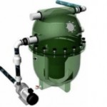
This shows just one example of the many units available, yes they do trap debris, they have to do but for how long they do this is another matter. As to how efficiently they get rid of this putrid collection that is building up constantly is also pure wishful thinking.
It also does not take a man of science to realise that this would be far more easily achieved by way of a very, very long tube with the same diameter bore of the pump outlet stuffed full of discarded ladies’ tights. But how to clean the tights periodically in order to remove the debris is another matter altogether!
The good news, for the numerous manufacturers, is that no one can actually SEE the time bomb that is ticking away within!
These units readily-available today are all derivatives of the original swimming pool sand filters used for many years and are still successfully used today for this purpose PURELY AS ‘MECHANICAL STRAINERS’. They do their excellent trapping and discharging work aided tremendously by chlorine bleach-based additives in the swimming pool water but please do not try this with fish!
Over the years many budding would-be ‘Koi entrepreneurs’ have picked up on these units whilst taking a swim and thought that this may be ‘a good earner’ if made to look revolutionary and very technical in appearance. The sad part is these people actually believe their ‘inventions’ work but I’ll bet not a single one of them even keeps fish – let alone Koi!
HORIZONTAL-FLOW PATTERNS
Horizontal-Flow patterns are also only mildly useful biologically if used in standard-sized boxes as follows: –
Again tracking takes place as can be seen in the animation and this produces no more than 20% overall efficiency.
But by narrowing the box and making it shallower and longer like a river as shown below and then placing more barriers inside this is what happens.
Again, exactly the same tracking occurs but, purely because there are three barriers to face, the distribution to surfaces is three times more than the earlier example but, by no means, being even near to be able to be termed as anywhere near ‘satisfactory’.
This is ERIC, a combination of:-
2. Contained within a Narrow, Shallow and Long box.
3. With Very Heavy Water Turbulence and thus total confusion in the CAPTIVE small spaces prior to each barrier.
This now produces an ever moving and totally captive ‘BLOCK’ of water as opposed to an invisible central channel. As this block moves forward endlessly at a rate dictated by the suction rate of the pump, it passes through the entire width and depth of the media barriers (more on these barriers later) to produce a staggering constant coverage of ALL media surfaces with an estimated 85% efficiency.
The animation below is the ERIC FOUR unit and will hopefully explain much better than words as to how the endless BLOCK of water moves along the river. The colours show ammonia-rich water in red which fades gradually as it passes through to the end of the river to show non-toxic blue water which is returned to the pond as shown. The black flecks entering the box from the bottom drain represent mechanical debris.
The ERIC FOUR unit holds 116 gallons (530 litres) of water; this example is based on a pumping rate of 1,400 gallons (6,360 litres) per hour. At this flow rate, the 116 gallons (530 litres) of water passes through the box once every 5 minutes and the five divisions below the animation represent minutes elapsed per ‘pass’. Each ‘pass’ is numbered to show the present ‘pass’ exiting the box and the new ‘pass’ entering the box.
There are two reasons for showing this animation.
The second reason is also important as a result of reason one above.
These are not my personal ‘opinions’ they are merely simple facts that any water-flow technician will confirm.
Whilst I do openly admit that ERIC systems, operated correctly, will only produce around 85%? flow rate efficiency to all biological surfaces (at a reasonable operating cost), in view of the other options available and their percentage results, I’ll settle for 85% efficiency in 2009!
Up to now, I have only outlined the outer box of ERIC and the water flow principles behind it. On the next page I will show the most more important parts that are contained within the box itself and exactly why the modern-day ERIC is so deadly in performance.


